

Fpc flexible circuit board test method and standard
- Categories:Company News
- Author:
- Origin:
- Time of issue:2021-03-08
- Views:
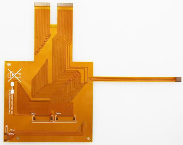
(Summary description)FPC flexible circuit board, English called Flexible Printed Circuit, commonly known as "soft board", also called flexible circuit board, is a kind of flexible insulating substrate made of polyimide or polyester film with high reliability. A stunning flexible printed circuit board. It has a unique place with high degree of wiring density, light weight, thin thickness, and good bendability. Flexible printed circuit boards are also divided into single-sided, double-sided and multi-layer boards.

Fpc flexible circuit board test method and standard
(Summary description)FPC flexible circuit board, English called Flexible Printed Circuit, commonly known as "soft board", also called flexible circuit board, is a kind of flexible insulating substrate made of polyimide or polyester film with high reliability. A stunning flexible printed circuit board. It has a unique place with high degree of wiring density, light weight, thin thickness, and good bendability. Flexible printed circuit boards are also divided into single-sided, double-sided and multi-layer boards.
- Categories:Company News
- Author:
- Origin:
- Time of issue:2021-03-08
- Views:
FPC flexible circuit board, English called Flexible Printed Circuit, commonly known as "soft board", also called flexible circuit board, is a kind of flexible insulating substrate made of polyimide or polyester film with high reliability. A stunning flexible printed circuit board. It has a unique place with high degree of wiring density, light weight, thin thickness, and good bendability. Flexible printed circuit boards are also divided into single-sided, double-sided and multi-layer boards.
The flexible circuit board is mainly used in the joint sign of electronic products. Its strength is that all lines are equipped and arranged. Eliminates the need for co-signing work; it can increase the softness. Enhance the assembly of three-dimensional space in a limited space; it can be effective to reduce the output and the size of the product. Increase the convenience of carrying; it can also reduce the weight of the final product.
The scope of this standard covers flexible circuit single-sided, double-sided and multilayer boards. The flexible circuit board mentioned in this standard refers to single, double and multilayer flexible copper foil substrates with polyimide (PI) or polyester (PET) as the base material. There are adhesives (Adhesive, 3L-FCCL) and adhesive-free (Adhesive, 2L-FCCL) flexible copper foil substrates.
The purpose of this standard is to establish a general rule for the identification of the appearance quality of related flexible circuit boards. As a basis for the identification of the appearance quality of soft board products between Tianpai enterprises and suppliers, it will help to improve the production technology and reduce damage. Resource consumption and background pollution caused by abandonment.
The attempts to explain clearly in this specification use visual inspection, magnifying glass, and rulers as the main inspection methods and tools. When indispensable, other suitable test spectrographs or facilities should be used for inspection and inspection.
1. Appearance of substrate film surface:
The scope of the substrate film surface appearance allowable deficiency where the conductor does not exist is listed in the table. Other bumps, creases, wrinkles, and attached foreign objects that affect the use are not allowed.
2, the appearance of the covering layer:
Imperfections in the appearance of the masking film and masking coating: Permitted range, concavities and convexities, creases, wrinkles and delamination that affect the application are not allowed.
3, the deviation of the signed disk and the cover layer:
The deviation between the co-signed disk and the cover layer is allowed to be less than ±0.3mm when the external dimension is less than 100mm, and when the external dimension is more than 100mm, the allowable deviation is less than ±0.3% of the external dimension.
4. The seepage of adhesive and covering coating:
The bleeding degree f of the adhesive and the covering coating should be less than 0.2mm. However, at the joint sign, plus the deviation of the cover layer and the deviation of the punching, you must be satisfied with the minimum ring width g≥0.05mm
5. Discoloration:
The conductor under the cover layer changes color. After the temperature is 40℃, the degree of humidity is 90%, and the humidity resistance test for 96 hours, it must still meet the requirements of voltage resistance, buckling resistance, bending resistance, and welding resistance.
6. Omission of coating:
The missing coating of the coating layer should be tried in accordance with the requirements of solderability. Tin should not be stuck on the conductor where the coating layer is missing.
7. Poor electroplating joint:
The plating layer is not allowed to have delamination, the width W1, the length L, the conductor width W after processing is not good for the plating bonding, and the poor bonding of the plating shall not impair the reliability of the contact area.
Scan the QR code to read on your phone
-
 Basic knowledge of FPC circuit board
With the continuous increase in the yield ratio of flexible PCBs and the application and promotion of rigid-flex PCBs, it is now more common to add soft, rigid or rigid-flex when talking about PCBs, and say that it is a few-layer FPC. Generally, an FPC made of a soft insulating substrate is called a soft FPC or a flexible FPC, and a rigid-flex composite PCB is called a rigid-flex PCB. It meets the needs of today's electronic products for high density, high reliability, small scale, and lightweight progress. It also satisfies the strict economic requirements and the needs of market and technology competition. - Fpc flexible circuit board test method and standard 03-08
- Interpretation of four-layer PCB circuit board stack design scheme 03-08
- What are the common rules for PCB wiring? 03-08
- PCB assembly quality and reliability control of electroless nickel-palladium-gold plating 03-08

Service Hotline:
Email:lhdpcb@vip.163.com
Address:No. 26, Meiyuan 3rd Road, Intercontinental Industrial Park, Luoyang Town, Boluo County, Huizhou
 0752-6260118

 QQ
QQ 

Copyright ©Huizhou Linghangda Technology Co., Ltd. All Rights Reserved 粤ICP备18145577号
Power by: www.300.cn